injection sleeve/and bolt tensioner
assembled on the other side of the
assembled double shear box. It was
held in place using another barrel and
wedge. The cable bolt was
pre‑tensioned to an axial load of 50 kN
by a torque wrench before grouting.
Grouting of the cable bolt in concrete
was achieved by pumping FB400 grout
into the hole containing the cable bolt
using grouting sleeve, and in
accordance with the established process
of grouting. Quad seals were used to
seal around the cable in the load cell
side of the concrete block in order to
protect the load cell from being
contaminated by the grout. Special
grout seals were used to minimise grout
outflow during pressure injection of the
grout. Air was allowed to escape from
one end of the assembled cable bolt
system and along the free cable strand
end as grout was pushed through the
hole length.
Testing procedure
The assembled double shear box
apparatus was then placed on a
carrier base frame, consisting of a
parallel pair of rail track sections
welded to a 35 mm thick steel plate.
The whole assembly was mounted
between the 600 x 600 mm loading
plates of the 500 t compression testing
machine as shown in Figure 3. The
outer 300 mm side concrete cubes
were seated on 75 mm high steel
blocks, leaving the central 450 mm
long block free to move vertically
down during the shearing process.
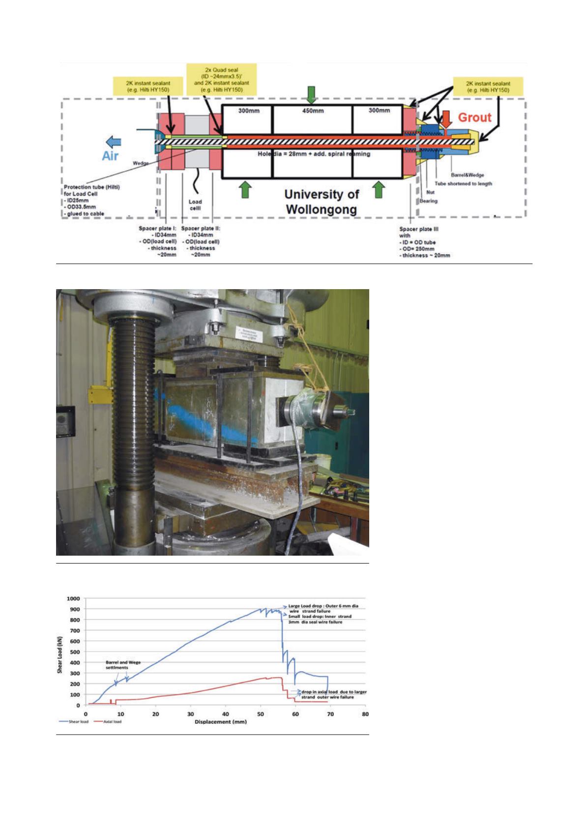
Figure 2. A schematic layout of the cable installation assembled in concrete blocks.
Figure 3. Double shearing apparatus loaded in 500 t Avery compression testing
machine.
Figure 4. Shear load and axial load vs vertical travel of the central block of the loaded
double shear apparatus.
28
|
World Coal
|
January 2016


