The rate of shearing of the
double shear apparatus for the
middle section was maintained
constant at 1 mm/min. for the
75 mm of vertical displacement.
The rate of loading and
displacement was monitored and
simultaneously displayed visually on
a PC monitor.
Results and analysis
Indented cable bolt
Figure 4 shows the applied shear load
and axial load in the cable vs the vertical
displacement of the central block of the
double shear apparatus with indented
cable bolt. The maximum vertical load
was 904 kN, which occurred when the
vertical travel of the central block
reached approximately 52 mm. The
maximum axial load developed at the
cable bolt was 254 kN.
Various shear load drops that
occurred beyond the vertical
displacement of 52 mmwere due to
individual cable strand failures (strand
snap). The relatively larger shear load
drop, post the 904 kNmaximum load,
was likely due to larger (5.5 mm dia.)
outer strands, as well as the central core
strand failures (7 mm dia.), while small
drops are indicative of the small 3 mm
dia. strand failure. It is interesting to
note that outer strand failures are also
marked by drops in the axial pretension
load on the cable bolt, as monitored by
the 60 t load cell. The number of visible
sudden drops on the load displacement
graph appears to be slightly less than the
total number of the 19 failed strands.
This is clearly evident from Figure 5
(left) of the failed/snapped cable section
as retrieved from dismantled blocks.
Characteristically, the snapped cable
strand ends depict strand failures, as a
combination of tensile and shear failures,
which would occur when the cable is
sheared in a rock mass. This kind of
failure is the result of bending of the
cable in the vicinity of the sheared plains
where the concrete has crushed for a
length of up to around 60 mm from the
sheared joint plains (Figure 5 right).
The loading changes Aand B,
shown in Figure 4, are attributed
possibly to wedge and barrel
settlement/adjustment during the early
start of cable bolt loading, as the cable
bolt begins to take extra axial load due to
the central/lateral shear loading.
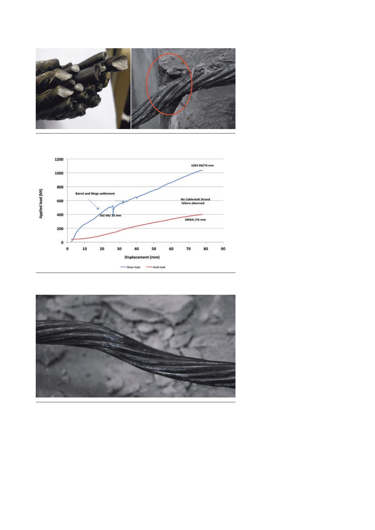
Plain strand cable
Figure 6 shows the load/displacement
profiles of the second test carried out on
22 mm dia. Hilti 19 plain strand cable.
The plain cable bolt reached a maximum
shear load of 1024 kN for the vertical
displacement of 75 mm. The maximum
generated axial load on the bolt was
400 kN. Similar to the indented strand
cable, there was a typical barrel and
wedge adjustment axial load drop
during the early part of the cable
shearing process. This settlement
occurred at 502 kN of vertical shear load
and at the vertical shear displacement of
Figure 5. (left) failed indented strand cable bolt and (right) concrete deformation
around sheared section of the bolt.
Figure 6. Shear load and axial load vs vertical travel of the central block of the loaded
double shear apparatus.
Figure 7. Post test plain strand cable. No strand failure.
30
|
World Coal
|
January 2016


