through the initial opening. As the
opening becomes larger, coarser material
and individual boulders slide out of the
skip into the crusher station bin or onto
a waiting truck. The hydraulic closing
and opening mechanism is mounted on
the skip and is activated in discharge
position by a plug in power/control
contact. Opening and closing of the
discharge flap takes place fully
automatically above a crusher station,
whereas operator control is envisaged
for truck re-loading.
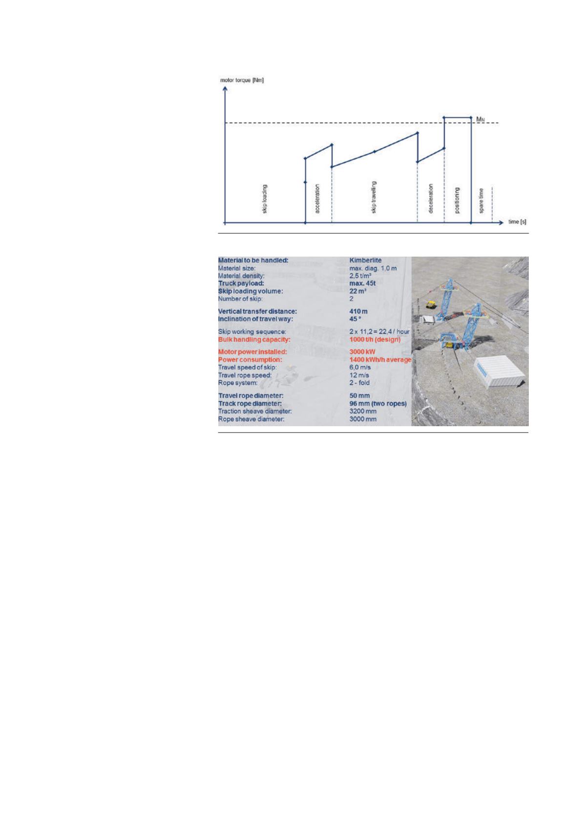
Characteristic design data for a Skip
Way System in a kimberlite mine are
shown in the example in Figure 7.
In the example presented, uncrushed
kimberlite with a density of 2.5 t/m
3
is
transported by a tandem Skip Way
System a vertical distance of 410 m over
a slope with an average incline of 45˚.
The mine trucks have a maximum
payload capacity of 42 t, so the skips
were designed for a capacity of 22 m
3
or
45 t max. With a conveying distance of
580 m and a chosen travel rope speed of
12 m/sec., this results in 11.2 travel
cycles per hour and rope system for a
handling capacity of 1000 tph.
Due to the heavy masses to be
accelerated and positioned, the drive
motor is designed for a power output of
3000 kW. During the steady-state phase,
i.e. during constant skip travel, skip
deadweight compensation comes fully
into play, so the average power
requirement – over the full travel cycle
– will be only 1400 kW. The deadweight
of a skip, including deflector sheave and
tandem carriage for a maximum
payload of 45 t, is 37 t. Of this, as much
as 22 t is accounted for by the skip and
hydraulic unit. This relatively high
deadweight is necessary to absorb the
heavy impacts of individual boulders
during loading, but it also serves to
tension the travel rope in the wrap drive.
The dead loads of the two skips do not
need to be considered, as the masses
cancel each other out exactly in
operation. The travel rope connecting
the skips runs over the traction sheave
with a speed of 12 m/sec. and moves the
skips after single deflection by a sheave
in the skip carriage with a maximum
speed of 6 m/sec.
The travel rope is 50 mm in dia. and
the two full-locked track ropes in each
strand are 96 mm in dia. In accordance
with the relevant design standards, the
design of the rope and the rope diameter
require a traction sheave diameter of
3200 mm and deflector sheaves with
3000 mm dia.
Depending on vertical lift and travel
distance, a Skip Way System can handle
up to 2000 tph. The actual handling
capacity and hence the maximum truck
payload is limited to 60 t per skip and is
determined by the rope construction,
rope breaking strength, rope diameter
and the allowable wheel pressure on the
track rope.
Completing the line up
The tk Skip Way System is highly
adaptable to the topography of the mine.
Depending on the location of haul roads,
the configuration of the edge of the
mine, the slope and space conditions at
the bottom and exit of the mine, the
drive station can be arranged in different
ways relative to the unloading stations
in the mine. The spacing and orientation
of the two masts – and thus of the truck
loading and crushing stations – can also
be varied to suit local conditions.
Examples of possible layouts at the rim
of the mine are shown in Figure 8. The
spacing of the truck unloading stations
at the bottom of the mine and the angle
of the rising track ropes can naturally
also be varied.
The tk Skip Way System has been
designed for efficient use as a
steep‑angle conveying system in
quarries and smaller but deep opencast
mines. The system ideally complements
the integrated crushing and skip
conveying systemwith handling rates of
up to 5000 tph for uncrushed ore or
overburden previously presented by
thyssenkrupp.
1
In this system, skips run
in opposite directions on a steel track
over a steep slope and can either empty
their payloads of up to 250 t into the feed
bin of a semi-mobile crusher or re-load
ore or overburden onto correspondingly
Figure 6. Typical torque curve of drive motor during upward travel of the skip.
Figure 7. Design data for a skip system with 1000 tph handling capacity.
March 2016
|
World Coal
|
37


