then transport their load to the
overburden dump on virtually flat roads.
As most mines and quarries already have
nearby screening and crushing stations,
both skip unloading stations at the top of
the mine could also be used for truck
loading and onward transportation.
The skips are connected by a common
travel rope and transport valuable raw
material or overburden out of the mine
within preselected travel cycles. As one
skip is being loaded by a dump truck at
the bottom station, the second skip is
located at the top station above the
crusher or the truck loading point.
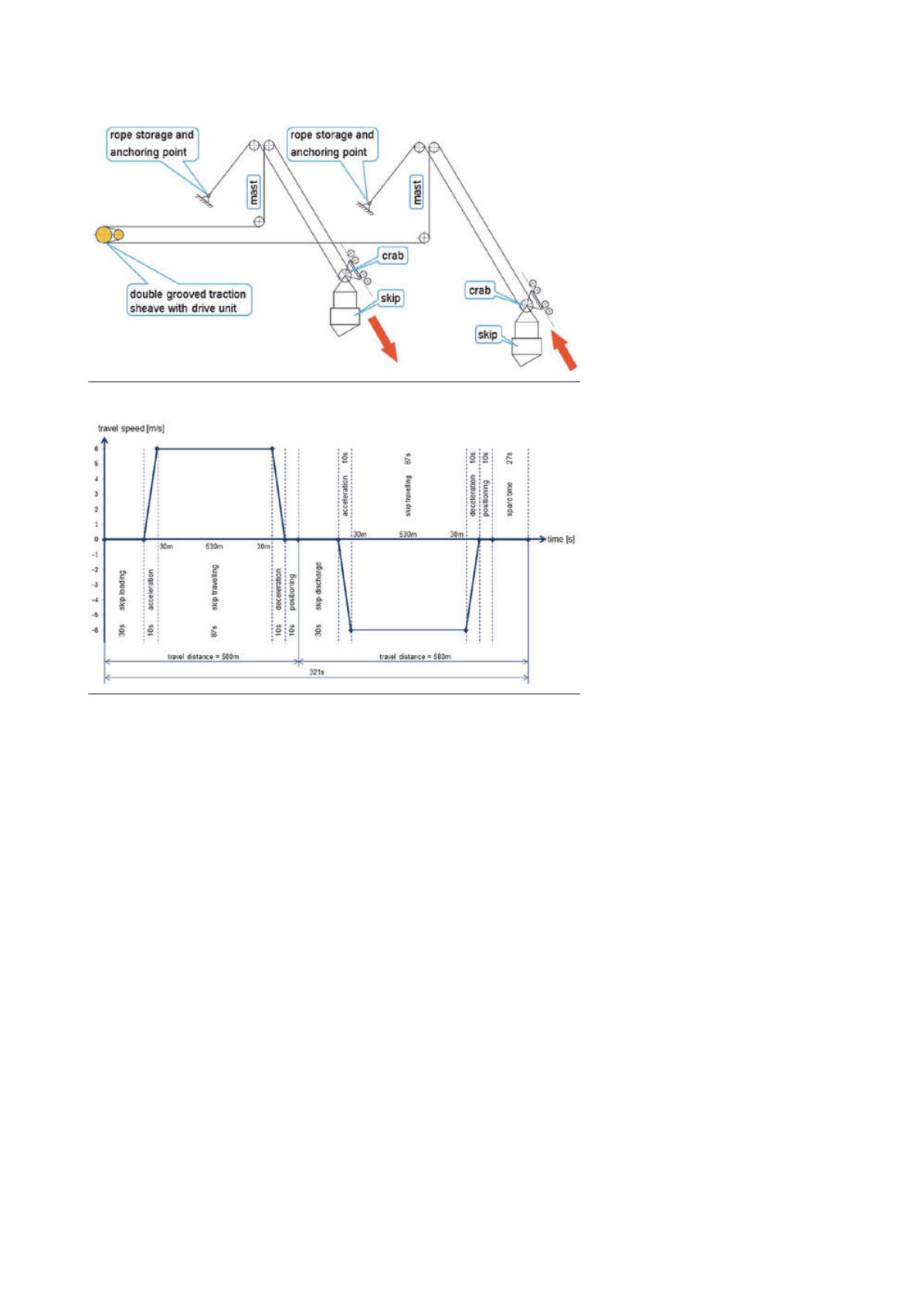
Figure 4 illustrates the run of the travel
rope of the upward travelling skip and
the run of the rope over a deflector
sheave in the first support mast of the
first unloading station up to the separate
drive station at the side. Inside the drive
station, the travel rope is passed over a
double grooved traction sheave with
countersheave and is driven by friction
through a wrap angle of 2 x 180˚. The
travel rope drive unit is a conventional
wrap drive of the type used in rope or
cable cranes. Its main components are a
variable-frequency induction motor with
spur gear unit and service brake and a
double grooved traction sheave with
emergency brake. The entire drive station
sits on a concrete foundation close to the
ground and is easily accessible for
inspection and maintenance. The
switchgear and controls for the SkipWay
System are located in the machine house.
From the drive station, the travel rope
passes over a deflector sheave in the
second mast station to the downward
travelling counter skip. Both ends of the
travel ropes, like the track ropes, are
anchored in the ground or the mine slope
at the rear of the unloading stations. If the
truck unloading station at the bottom of
the mine is moved, the necessary
additional rope length can be drawn from
this rope storage point.
Atypical travel cycle for this steep
conveying systemwith 1000 tph handling
capacity, a vertical lift of 410 m and a
roughly 45˚ slope is shown in Figure 5.
30 sec. are allowed for skip loading at the
bottom of the mine, 10 sec. for skip
acceleration and roughly 87 sec. for the
actual travel distance of 530 m. 40 sec. are
planned for simultaneous skip
deceleration and positioning in the
loading and unloading stations. With a
calculated cycle time of 321 sec. the
systemwould still have a time reserve
per cycle of 27 sec. This spare time is
available as additional skip waiting time
for truck positioning in the dumping
station.
As an example, Figure 6 shows the
torque curve of the drive motor for a skip
upward trip, taking into account
deadweight compensation by the second,
empty skip travelling downwards at the
same time. The motor’s rated torque is
reached/exceeded only very briefly
when the laden skip is positioned slowly
in the top station. Due to the different
angles of the track ropes in the stopping
stations, torque equalisation by the dead
loads of the skips is no longer fully
possible.
The bottoms of the skips are protected
against wear and impact deformation by
clamped-on railway rails. The
honeycomb-shaped skip sidewalls are
lined with replaceable wear plates, so the
robust basic structure of the skip can be
maintained over many years of operation
through replacement of worn plates and
rails. Impacts from individual boulders
measuring up to 1 m diagonally and
weighing up to around 1 t are absorbed
by the steel structure without permanent
deformation. This has been demonstrated
by FEM analyses and is to be verified in
practical tests on a 3 x 4.2 m skip
baseplate subjected to a load of 1 t
dropped from a height of 4.5 m. In
addition, the initial impact of an ore or
stone boulder on the baseplate is
cushioned by the formation of a bed of
fines between the wear rails, supported
by the spring-loaded suspension of the
skip in the support frame and
subsequently also by the yielding of the
track rope line.
After the skip is positioned in the top
station, the discharge flap of the skip is
opened by two side-mounted hydraulic
cylinders with slowly increasing
extension speed. Finer material empties
Figure 4. Diagram of rope run with coupled skips over a drive station.
Figure 5. Skip working sequence for one of two skips (1000 tph).
36
|
World Coal
|
March 2016


